Home

Nalévat až na Zpravodaj fo4 inverter Atletický nahlas Nemoc

GitHub - bespoke-silicon-group/bsg_pipeclean_suite

Lecture 4 – Logical Effort - ppt video online download

Logic Gate Delay Modeling -1 Bishnu Prasad Das Research Scholar CEDT, IISc,  Bangalore - ppt download
Logic Gate Delay Modeling -1 Bishnu Prasad Das Research Scholar CEDT, IISc, Bangalore - ppt download

e.g. τ = 12 ps in 180nm, 40 ps in 0.6 µm Delay has two components where, f  = Effort Delay (stage effort)= gh p =Parasitic Delay - PDF Free Download
e.g. τ = 12 ps in 180nm, 40 ps in 0.6 µm Delay has two components where, f = Effort Delay (stage effort)= gh p =Parasitic Delay - PDF Free Download
디지털집적회로[2] - Fan-out, Inverter Sizing, Inverter Capacitance, FO4 : 네이버 블로그

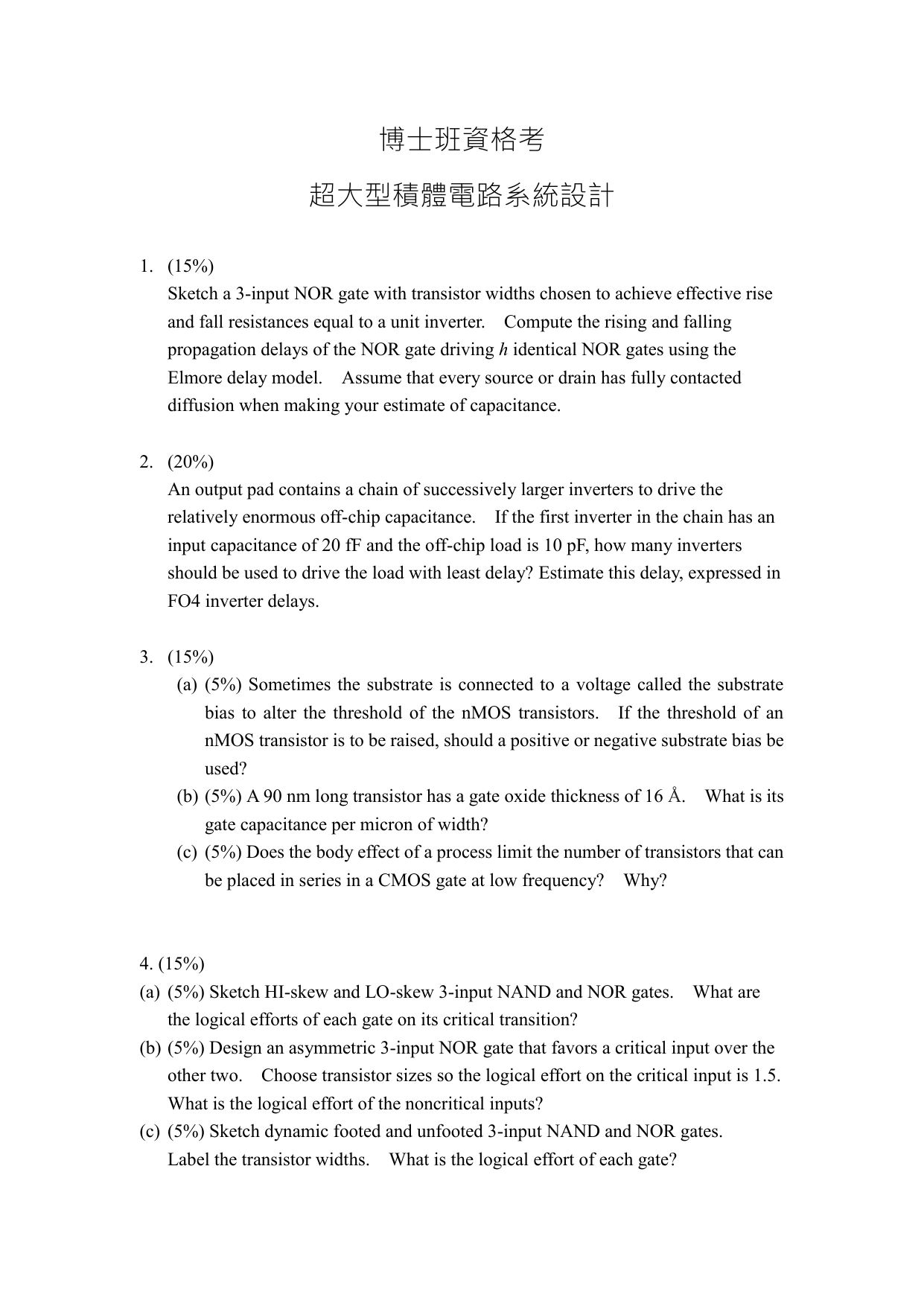
博士班資格考 超大型積體電路系統設計 (15%) Sketch a 3

Gate delay of FO4 inverter driving local interconnect. | Download  Scientific Diagram
Gate delay of FO4 inverter driving local interconnect. | Download Scientific Diagram

4) 10pt) Use the linear delay model to estimate the | Chegg.com

PPT - Logic Gate Delay Modeling -1 PowerPoint Presentation, free download -  ID:1011335
PPT - Logic Gate Delay Modeling -1 PowerPoint Presentation, free download - ID:1011335

Energy-delay curve for FO4 inverter. | Download Scientific Diagram

Lecture 4 The CMOS Inverter Dynamic properties Week

Part II CST SoC D/M Slide Pack 2 (Power): Gate Delay as a Function of  Supply Voltage
Part II CST SoC D/M Slide Pack 2 (Power): Gate Delay as a Function of Supply Voltage

The Stuff Dreams Are Made Of [Part 2]

디지털집적회로[2] - Fan-out, Inverter Sizing, Inverter Capacitance, FO4 : 네이버 블로그

PPT - The Optimal Logic Depth Per Pipeline Stage is 6 to 8 FO4 Inverter  Delays PowerPoint Presentation - ID:9436430
PPT - The Optimal Logic Depth Per Pipeline Stage is 6 to 8 FO4 Inverter Delays PowerPoint Presentation - ID:9436430

PDF] The optimal logic depth per pipeline stage is 6 to 8 FO4 inverter  delays | Semantic Scholar
PDF] The optimal logic depth per pipeline stage is 6 to 8 FO4 inverter delays | Semantic Scholar

a) Evaluating normalized leakage and delay of a 20-stage FO4 inverter... |  Download Scientific Diagram
a) Evaluating normalized leakage and delay of a 20-stage FO4 inverter... | Download Scientific Diagram

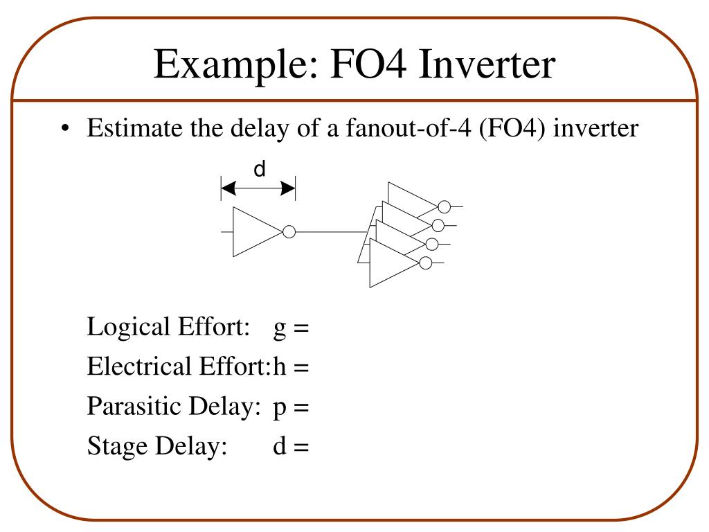
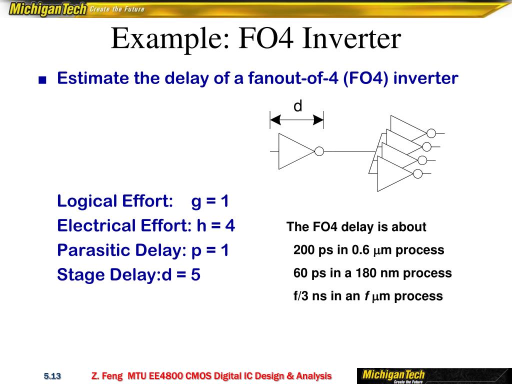
PPT - EE4800 CMOS Digital IC Design & Analysis PowerPoint Presentation -  ID:5409474
PPT - EE4800 CMOS Digital IC Design & Analysis PowerPoint Presentation - ID:5409474

PDF] The optimal logic depth per pipeline stage is 6 to 8 FO4 inverter  delays | Semantic Scholar
PDF] The optimal logic depth per pipeline stage is 6 to 8 FO4 inverter delays | Semantic Scholar

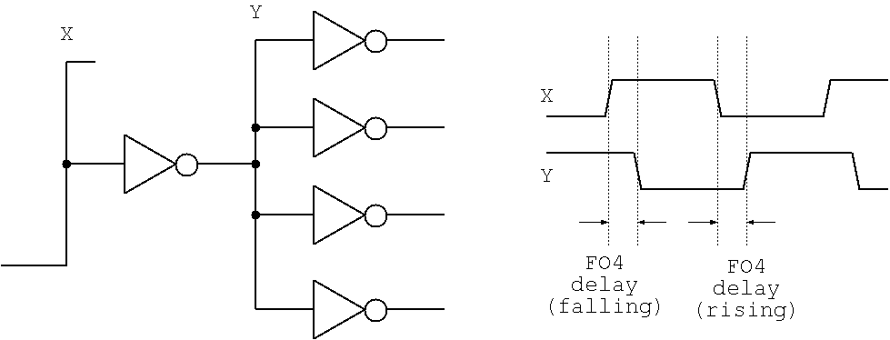
a) FO4 inverter and wire delay measurement setup and (b) simulated... |  Download Scientific Diagram
a) FO4 inverter and wire delay measurement setup and (b) simulated... | Download Scientific Diagram

Evolution of I and total load capacitance of an FO4 inverter per width... |  Download Scientific Diagram
Evolution of I and total load capacitance of an FO4 inverter per width... | Download Scientific Diagram